Network Visualization nuVML™ Virtual Modeling Lab
Quick Start Guide
Version 1.1 | June 12th, 2017
Introduction
What Is nuVML™?

nuVML™ is a network visualization tool
It allows for abstract virtual logical visualization of the relationships between physical and virtual network devices. It visualizes routing protocols, traffic flow, network topology changes in real-time.
nuVML™ can run as a stand-alone application or in conjunction with Cisco VIRL and CML. It supports multi-vendor environment, works seamlessly with all node types that are simulated in Cisco VIRL and CML.
Who Should Use nuVML™?
For individual and educational purposes
Combined with Cisco VIRL, individuals who are studying for CCNA, CCNP and CCIE certifications, training and learning about network technologies, it helps instructors to teach, and students to learn and build labs in virtual environment. With 2D and 3D views of packet flow inside your network in real-time, it makes the learning easy and fun.
For businesses and network engineers
nuVML™ can be used for network design, capacity planning, proof of concept, change validation, “what-if” scenario testing and more. It empowers new generation of network design, modeling and simulation solutions with discovery & visualization for production, simulated, hybrid networks, substantially mitigating risks.
Key Features
- Design and build network topology
- Start virtual instances and discovery topology inside
- Source and destination path selection for routing visualization
- Discovery and auto-build topology using NVRAM configuration
- Re-route path and dynamic route switching. Access-list filtering
- Visualize LDP, MPLS/VPN, VRF, DMVPN Phase 1,2,3
- Visualize and monitor eBGP/iBGP peers and prefix changes
- PE to PE, PE to CE multi-protocol visualization and Auto Display
- Discover production network and create a virtual replicate lab
- Switching visualization production network of Trunks/SVI VLANs
- Visualize Trunk/Tunnels in DNA View and 3D Topology View
- RIP, EIGRP, OSPF and BGP support
- EIGRP Process and OSPF Areas visualization
- End to end Tunneling & GRE visualization
- Network Service Protocol Visualization
- SNMP Discovery Network Management
- Troubleshoot network issues in real time
- Visualized “what if” Link Failure scenario behaviors
- HSRP/VRRP visualization
- Discovery logical lab or production network configuration
- Import and Export network topology to MS Visio files
- Import and Export network node configuration
- Real time packet capturing
- Download standard .cap file use in Wireshark
Getting Started
System Requirements
Operating System
– Microsoft: Windows 7, 8 and 10
– CPU i5, i7 and newer
– 64‐Bit
– Microsoft.NET Framework 4
You need Administrator’s privilege on the PC to install and run the application successfully.
Mac OS is not supported at this time.
CPU Processor
– 2.0 Ghz minimum, 4 logical cores
Memory
– 8GB recommended
Hard Drive
– Client requires 100GB of storage
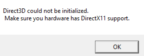
GPU / Video Card (important)
– AMD Radeon or better
– NVidia GeForce video card with DirectX 10.1(11) or better
If your computer does not have a supported graphic card, you will receive a warning message.
Display Resolution
– We recommend 1920×1080
– GUI will function at lower resolutions
Installation
Step 1: Download the .zip installation package
Once you made payment online, you’ll receive an email shortly after with a download link. Click the link to download the installation page. Note the download link is a randomly generated link and will expire in 72 hours. If you did not download the installation file after the link expires, please contact support with your order number.
Extract the .zip file and save the folder on your computer.
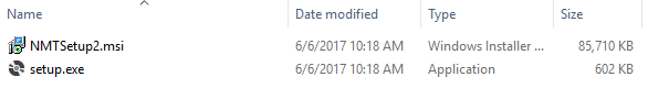
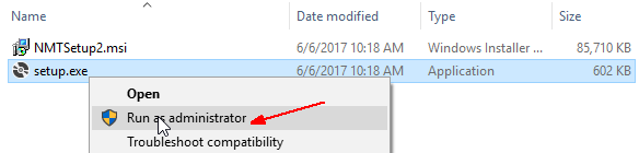
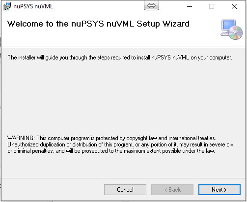
Step 2: Run the installer and install nuVML on your computer
Right-click on “setup.exe” and select “Run as administrator” to start the installation.
For Windows 7 and Windows 10, you may see warning messages as shown below. Click on “More info” and “Run Anyway” to continue.

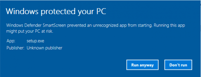
Note: You received this message because nuVML is a new application and its developer signature has not been recognized by Microsoft. It is completely safe to continue the installation.
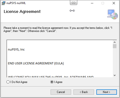
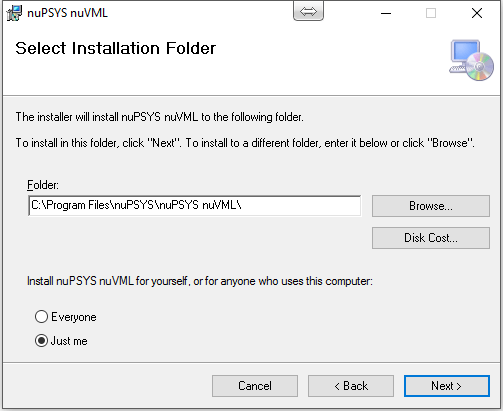
The remaining installation steps are straightforward. You may use default settings to complete the installation.
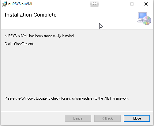
Now you have successfully installed nuVML on your computer.

Step 3: License activation
Right-click on the “nuPSYS VML” icon on your desktop while holding the “Shift” key. Click “Run as administrator”.
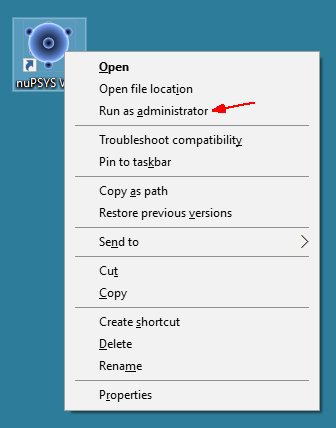
It is important that you run nuVML as administrator for the first time to activate its license. Once activated, you don’t need to run in admin mode in the future.
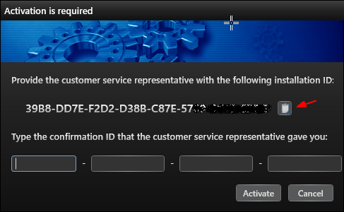
The process of activating your license is as following:
- Copy your “Installation ID” from the Activation window.
- Go to nupsys.com and open a Live Chat session. Tell the support representative that you have purchased nuVML and need your license activated.
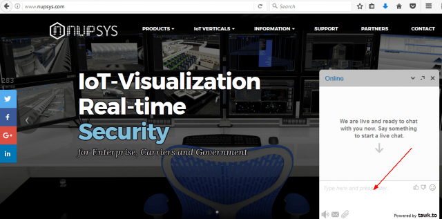
- Provide your “Installation ID” and “Order number” to the Live Chat representative. And he or she will generate a “Confirmation ID”.
- Copy and paste the “Confirmation ID” into your Activation window and click “Activate”. Now you have successfully activated your license.
Visualize Your Simulation
Backend VIRL/CML Server Tuning
By default, VIRL/CML server does not allow longer packet capture session to run. You must increase the packet capture session limits to see best performance of nuVML.
sudo crudini --set /etc/virl/common.cfg limits tap_session 99
sudo service virl-std restart
sudo service virl-uwm restart
Design Network Topology
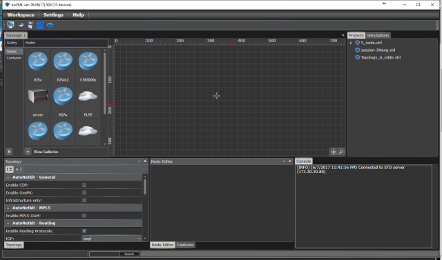
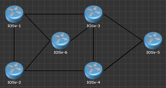
Step 1: Create a network topology
Select a note type, for example a IOSv router from the left window and place it on the topology canvas. You may put multiple, different types of network nodes and connect them by click and hold your mouse key.
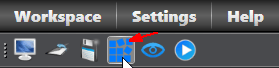
Step 2. Build configuration
Once the network layout is created, you may use “AutoNetkit” to generate a set of default configuration for the entire virtual network. Click “Build Configuration” icon on the menu.
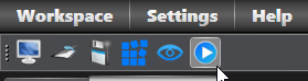
Running Simulation
Now the baseline configuration has been generated for all the nodes.
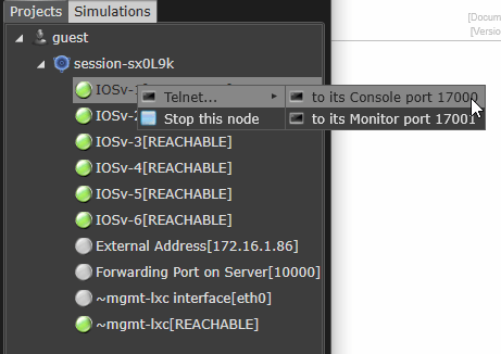
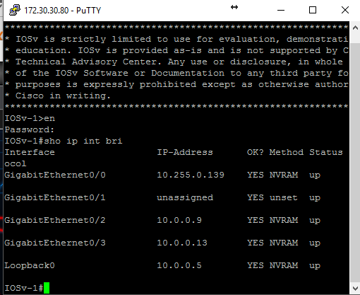
You may run the simulation by clicking on “Run” icon. Wait till all the node status becomes “Reachable”. You can connect to the node’s console port by right-click on the node name, and select “Telnet – to its Console port”.
Live Traffic Visualization
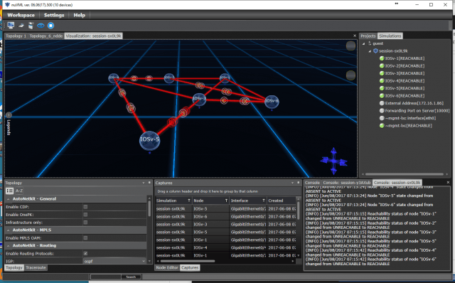
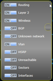
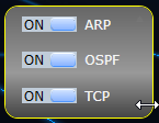
Once all the network nodes are up and running, you’ll see packets flow among them. Different protocols are coded in different colors. You may choose to hide or show specific network protocols by turning the On/Off switches.
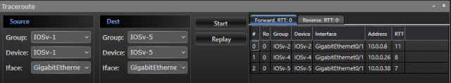
We can do a simple trace route to see traffic traversing the network.
Discover Production Network
How Discovery Works
One of the key features of nuVML offers is Network Discovery. The network being discovered can be virtual or physical network infrastructures. nuVML utilizes multiple methods to gain access and collect network information from the routers. It uses Telnet, SSH, SNMP, Ping Sweep, STD API and NVRAM Configurations to probe the network environment. In case of leveraging credentialed discovery by Telnet or SSH, nuVML only needs to access one of the core routers. All other routers are discovered based on routing table database (i.e. OSPF, EIGHT and BGP), CDP, and ARP. Once network nodes are discovered, they are presented in 3D view. Router interfaces (logical and physical), routing protocols and traffic flows are displayed in a visual and multi-colored view. In case of discovery production network, a very complex multi-layered datacenter network or service provider network can be visualized. To utilize the Network Discovery module, you do not need a simulation engine such as Cisco VIRL or CML. Discovery is a standalone module for nuVML small business and enterprise editions.
Run Discovery
The only requirements for Network Discovery are:
- nuVML shall have IP reachability to one of core routers
- For credentialed Discovery, you need to provide a Telnet / SSH account.
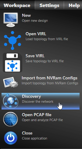
Step 1: Go to menu “Workspace” and click on “Discovery”.
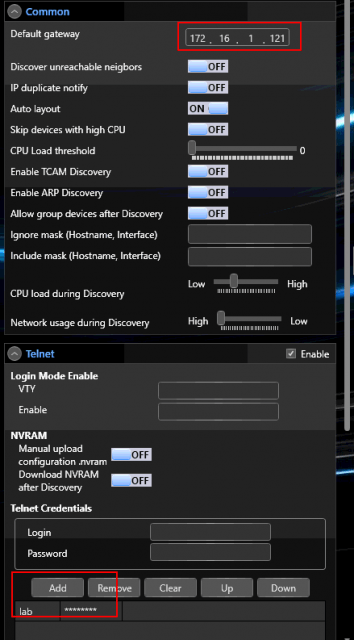
Step 2: Expand “Common” and supply one of the core router’s IP address in “Default Gateway” field.
Step 3: Supply a login account for Telnet or SSH. And click “Start Now”.
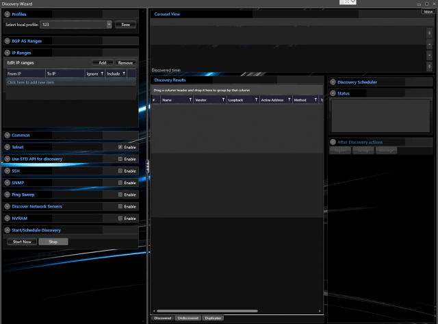
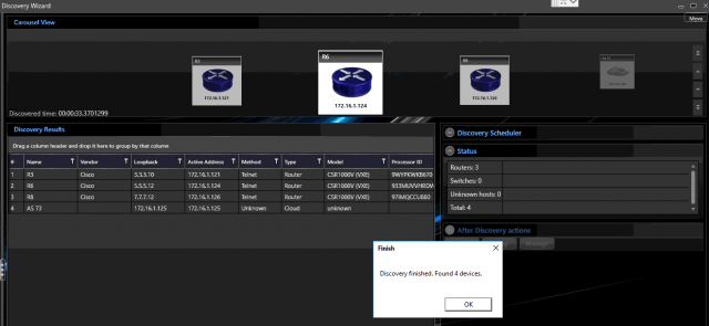
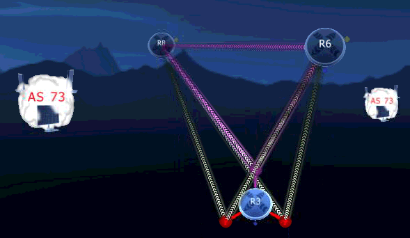
Step 4: Wait till Discovery has completed. Close the Discovery window and go back to the main platform. The network has been presented in a 3D multi-colored view. You may zoom in/out, pan, tilt and rotate the topology using mouse.
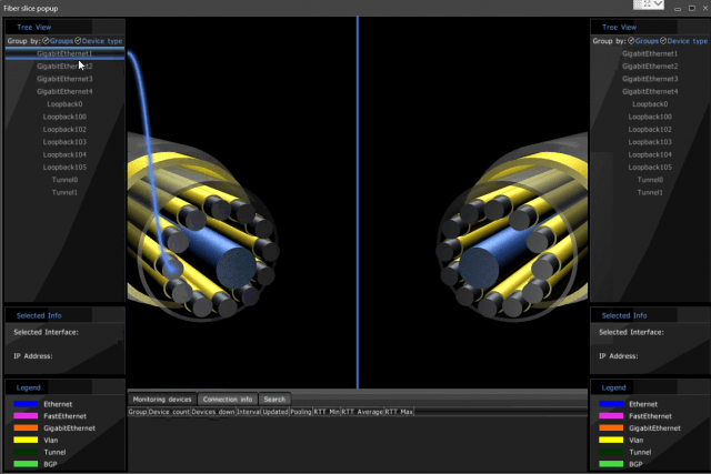
Interface Slice View
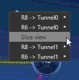
Highlight one of the links between two routers. Right-click and select “Slice view”. Now you can see all the physical and logical network interfaces on a router and how they are connected to its neighbor.
Tools and Tips
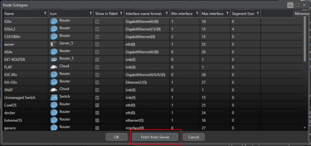
Import Additional Node Flavors
Using Cisco VIRL or CML as the backend simulation engine, you may import additional node subtypes from the server. Go to menu “Settings” and click on “Flavors”. Click on “Fetch from server”. A complete list of supported Cisco and Linux virtual note types can be imported. You can also determine which ones to show by selecting the check boxes.
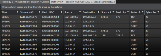
Real-time Packet Capture
Once you connected to a simulated network on Cisco VIRL or CML, you can display live traffic via packet capture. In “Captures” window, select a router interface. Right-click and select “View traffic”.
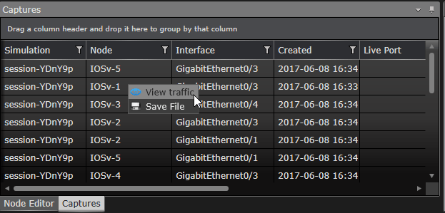
A packet capture window will open. It displays live traffic going in and out through this particular interface. You may also save the packet capture to a file and analyze it using Wireshark.
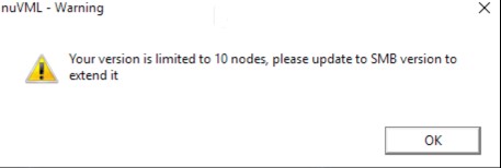
If you are trying to start a simulation that contains more nodes than your license allows, you’ll receive a warning messages. Although the simulation will still start and run, the 3D visualization view will be limited to the number nodes per license allows.
To learn more about the network visualization tool, please go to nuVML™ Virtual Routing Lab.