As the internet bandwidth becomes cheaper, organizations have upgraded their primary circuits to higher capacity circuits with lower cost. Some choose to keep their legacy service provider as a backup circuit. BGP is enabled on the Customer Edge (CE) routers to provide redundancy and load balancing. However given the nature of BGP is a path or distance vector routing protocol, it does not take bandwidth and circuit costs into consideration when making routing decisions. The question comes that how can we design a network so that the circuits with higher capacity and cheaper costs are utilized first. We keep the lower bandwidth or/and higher cost circuit as an “active” backup without losing the automatic failover provided by BGP. In this session, we’ll cover automatic ISP failover over uneven bandwidth circuits using HSRP, IP SLA and BGP technology.
First let’s get familiar with the basic network topology.
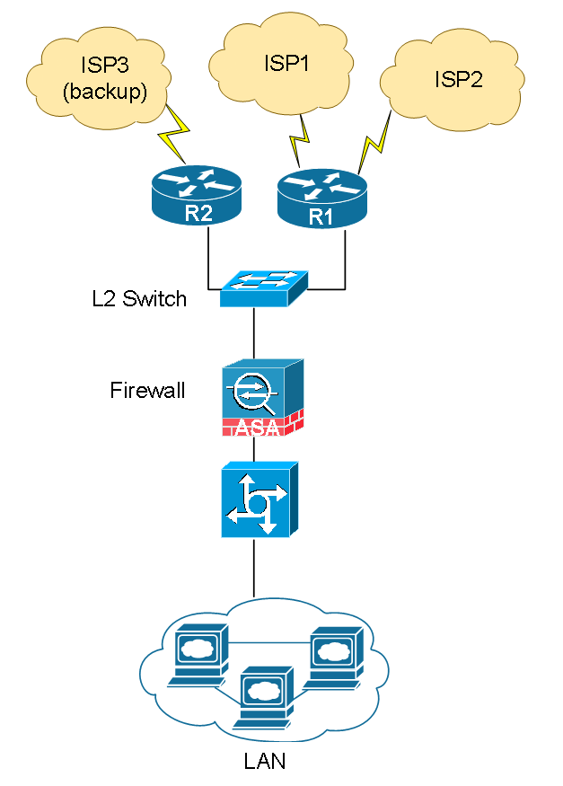
Network overview
- A network is comprised of three ISPs and two WAN routers R1 and R2.
- Two high capacity Internet circuits from two ISPs are terminated on R1. We use them as primary circuit.
- A lower capacity, high cost Internet circuit is terminated on R2. We only want to use it when both primary ISPs are down.
- WAN circuits failover and fail back should happen in automated fashion.
Design Principle
If there was only R1 with two ISPs, the design is rather simple. With the consideration of R2 and its backup ISP, we need to make sure the network is aware of its existence and automatically shifts traffic to R2 when R1 fails.
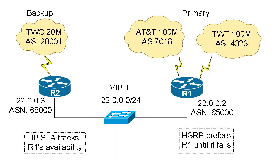
The first step is to establish basic BGP connectivity on all three WAN routers with their upstream ISPs. Since we are not a service provider providing Internet transit, and we want to conserve router resources, we’ll configure the WAN routers only to receive ISP’s directly connected prefixes and default route. Because the circuits on R1 have much higher bandwidth capacity, we want to use them for all outbound and inbound traffic. Let’s break down the “outbound” and “inbound” into two separate discussions. Here is our network diagram with IP information.
Outbound traffic
For outbound traffic, as long as the WAN router has a default route pointing to its upstream provider, user traffic can be forwarded to the Internet. In our case, three WAN routers each learn a default route from their upstream provider. R1 is preferred over R2 to act as the Internet gateway for internal users. This is done by configuring Hot Standby Routing Protocol (HSRP). A VIP is configured with R1 acting as the live gateway. R2 keeps track of R1’s availability, and it takes over R1’s role as soon as R1 is detected down.
Inbound traffic:
When BGP announces our prefix (22.0.0.0/24) to the Internet over multiple ISPs, it is known by other ISPs that there are more than one ways to reach us. This is where the distance-vector BGP routing protocol comes to play. When a user on the Internet wants to reach us, the user’s ISP looks at its routing table and figure out the best and shortest path to connect to our WAN routers. There are many BGP attributes to be considered when making routing decisions. For now, you can think of the shortest path to reach us is the best route to be chosen. What if we don’t want ISP3, the TWC backup circuit to be ever chosen unless it is the only option? There are several techniques we can use to “influence” the Internet to less prefer using ISP3 to reach us. Please note the word “influence”. There is no guarantee that the ISP will not be chosen. The techniques includes prepending AS numbers, using BGP community to advise your upstream provider to less prefer the prefix you announced to them and etc. But they all come with some caveats. Prepending AS numbers works in some cases but it never worked well in real world because AS Path is not the only attribute the Internet transit ISPs evaluate when making routing decisions. Using BGP community to advise your upstream ISP can only affect your directly connected ISP and its peering ISPs. Many times it is a manual process when you have to change the community or withdraw the announcement.
Our design concept works as following: R2 does not announce our prefix until R1 is declared down. We use IP SLA to track the availability of R1, and tell BGP to begin announcing the prefix in case R1 becomes unavailable. In this design, we have full control of when the backup ISP3 is being activated.
Configuration
Step 1: Establish eBGP peering with upstream service providers on each WAN router
On R1 we are peering with AT&T (ASN7018) TWT (ASN4323). And on R2 we are peering with TWC (ASN20001).
! R1
router bgp 65000
no synchronization
bgp log-neighbor-changes
network 22.0.0.0 mask 255.255.255.0
neighbor 12.12.12.1 remote-as 7018
neighbor 12. 12.12.1 description ATT
neighbor 12. 12.12.1 soft-reconfiguration inbound
neighbor 12. 12.12.1 prefix-list ATT-7018-OUT-FILTER out
neighbor 12. 12.12.1 prefix-list ATT-7018-IN-FILTER in
neighbor 12. 12.12.1 route-map ATT-7018-INBOUND in
neighbor 12. 12.12.1 maximum-prefix 600000 95 warning-only
!
neighbor 206.206.206.1 remote-as 4323
neighbor 206.206.206.1 description TWT
neighbor 206.206.206.1 soft-reconfiguration inbound
neighbor 206.206.206.1 prefix-list TWT-4323-OUT-FILTER out
neighbor 206.206.206.1 route-map TWT-4323-INBOUND in
neighbor 206.206.206.1 maximum-prefix 600000 95 warning-only
no auto-summary
no synchronization
end
Notice the prefix-list and route-map configured within the BGP session. The prefix-list restricts what prefixes we may announce to the Internet. We can only announce /24 or larger public IP blocks that assigned by Internet address authorities and registries. In our example, it is the 22.0.0.0/24 block. The route-map ensures what we get from our upstream providers. We want to make sure we don’t get more than what we asked for because excessive amount of routing information can overwhelm the router and impact performance. maximum-prefix warning is also a good practice to let the router send out syslog warning messages when the amount of prefixes received from upstream exceeded the number defined.
! AT&T inbound and outbound prefixes-lists
ip prefix-list ATT-7018-IN-FILTER seq 10 deny 0.0.0.0/8 le 32
ip prefix-list ATT-7018-IN-FILTER seq 20 deny 10.0.0.0/8 le 32
ip prefix-list ATT-7018-IN-FILTER seq 40 deny 127.0.0.0/8 le 32
ip prefix-list ATT-7018-IN-FILTER seq 50 deny 169.254.0.0/16 le 32
ip prefix-list ATT-7018-IN-FILTER seq 60 deny 172.16.0.0/12 le 32
ip prefix-list ATT-7018-IN-FILTER seq 70 deny 192.0.2.0/24 le 32
ip prefix-list ATT-7018-IN-FILTER seq 80 deny 192.168.0.0/16 le 32
ip prefix-list ATT-7018-IN-FILTER seq 90 deny 224.0.0.0/3 le 32
ip prefix-list ATT-7018-IN-FILTER seq 100 deny 0.0.0.0/0 ge 25
ip prefix-list ATT-7018-IN-FILTER seq 110 deny 22.0.0.0/24 le 32
ip prefix-list ATT-7018-IN-FILTER seq 9999 permit 0.0.0.0/0 le 32
!
ip prefix-list ATT-7018-OUT-FILTER seq 10 permit 22.0.0.0/24
ip prefix-list ATT-7018-OUT-FILTER seq 9999 deny 0.0.0.0/0 le 32

! TWT inbound and outbound prefixes-lists
ip prefix-list TWT-4323-IN-FILTER seq 10 deny 0.0.0.0/8 le 32
ip prefix-list TWT-4323-IN-FILTER seq 20 deny 10.0.0.0/8 le 32
ip prefix-list TWT-4323-IN-FILTER seq 40 deny 127.0.0.0/8 le 32
ip prefix-list TWT-4323-IN-FILTER seq 50 deny 169.254.0.0/16 le 32
ip prefix-list TWT-4323-IN-FILTER seq 60 deny 172.16.0.0/12 le 32
ip prefix-list TWT-4323-IN-FILTER seq 70 deny 192.0.2.0/24 le 32
ip prefix-list TWT-4323-IN-FILTER seq 80 deny 192.168.0.0/16 le 32
ip prefix-list TWT-4323-IN-FILTER seq 90 deny 224.0.0.0/3 le 32
ip prefix-list TWT-4323-IN-FILTER seq 100 deny 0.0.0.0/0 ge 25
ip prefix-list TWT-4323-IN-FILTER seq 110 deny 22.0.0.0/24 le 32
ip prefix-list TWT-4323-IN-FILTER seq 9999 permit 0.0.0.0/0 le 32
!
ip prefix-list TWT-4323-OUT-FILTER seq 10 permit 22.0.0.0/24
ip prefix-list TWT-4323-OUT-FILTER seq 9999 deny 0.0.0.0/0 le 32
In the inbound prefix-list, line sequence from 10 through 110 listed all the prefixes that should never appear on the Internet routing table. Those prefixes are either reserved for research purpose, multicast IP space defined by IPv4 RFC, or, private IPs that should never be routed on the Internet. Also, if the router sees our own prefix 22.0.0.0/24 being announced by upstream provider, we do not want to inject the route ether. Once the routing information passed the prefix-list inspection, it may come in. Very often, attacks and hackers on the Internet spoof their source IPs by using one of the IPs in the list above to carry out the attacks. It is the best practice to implement an extra layer of protection when configuring BGP.
The outbound prefix-list is straightforward. It allows only our prefix 22.0.0.0/24 to be announced to the upstream.
When you request your upstream ISP to peer with you, they will ask what types of routes you want to receive from them. Typically there are 4 options: default route only, default route + ISP routes, ISP routes + their customer routes, and finally the entire Internet routing table. As the time of this article is written, there are about 550,000 routes on the Internet routing table. There is no use for you to receive the entire Internet routing table unless you are an ISP providing IP transit, or for research purpose.
Although you can rely on your ISP not to send the entire Internet routing table to you, in case they messed up their configuration, we want to protect our routers. The configuration below filters the routes received from the upstream ISP and only places the ISP native routes originated from itself, and their customers’ routes into our BGP routing table.
ip as-path access-list 1 permit ^7018_[0-9]*$
ip as-path access-list 2 permit ^4323_[0-9]*$
!
route-map ATT-7018-INBOUND permit 10
match as-path 1
route-map TWT-4323-INBOUND permit 10
match as-path 2
R2 has the similar configuration that we will not cover in details.
Step 2: Configure HSRP on R1 and R2’s internal interface. Give R1 the preference of active Internet Gateway for internet users.
R1 and R2’s configuration is shown below. There are two key features in this configuration:
- R1 is set with HSRP priority 105 (R2 uses default 100). R1 becomes the active router serving 22.0.0.1
- “track 1” is configured to watch whether the default route 0.0.0.0 /0 is still being leant from the upstream ISP. If the default route disappears, most likely it has lost upstream connection for whatever reason, all outbound traffic will stale. When that happens, a router cannot act as active gateway for users. R1 decrements 10 from its priority 105 and becomes 95. R2 has primary 100 and will take over R1’s role immediately.
! R1
interface GigabitEthernet0/1
description LAN
ip address 22.0.0.2 255.255.255.0
standby 1 ip 22.0.0.1
standby 1 priority 105
standby 1 preempt
standby 1 track 1 decrement 10
end
track 1 ip route 0.0.0.0 0.0.0.0 reachability

! R2
interface GigabitEthernet0/1
description LAN
ip address 22.0.0.3 255.255.255.0
standby 1 ip 22.0.0.1
standby 1 preempt
standby 1 track 1
end
track 1 ip route 0.0.0.0 0.0.0.0 reachability
Show commands verify the status of HSRP and track objects.
R1#sho standby brief
P indicates configured to preempt.
|
Interface   Grp Pri P State   Active         Standby     Virtual IP
Gi0/1       1   105 P Active local           22.0.0.3     22.0.0.1

R1#sho track 1
Track 1
IP route 0.0.0.0 0.0.0.0 reachability
Reachability is Up (BGP)
2 changes, last change 23w0d
First-hop interface is FastEthernet0/0/0
Tracked by:
HSRP GigabitEthernet0/1 1
Step 3: R2 withdraws BGP announcement unless R1 fails
Think about the current situation for a moment. If you stopped at Step 2, all outbound traffic goes through R1 for Internet and the inbound traffic may still go through R2. Recall the requirement, we do not want any traffic go through R2 unless R1 fails. Therefore, we need to configure conditional routing that only activates R2 when R1 fails.
At this time, all the magic happens on R2. We first configure an IP SLA monitor, which keeps track of the reachability of R1’s Ggi0/1 22.0.0.2. It pings R1 once every 60 seconds and repeats indefinitely. “track 2” is configured to watch “ip sla monitor 1”, and declare down state after 90 seconds ( track 1 is in use to track 0.0.0.0/0). Reinstate up state after 120 seconds when the monitor is up.
ip sla monitor 1
type echo protocol ipIcmpEcho 22.0.0.2 source-interface GigabitEthernet0/1
ip sla monitor schedule 1 life forever start-time now
!
track 2 rtr 1 reachability
delay down 90 up 120
A static Null route is used to let BGP processor know a Boolean state: true or false. The actual route does not matter. We chose to use a host route with a non-publically routable IP. This configuration states: install the static route into our routing table only when “track 2” is up. Remove this route when “track 2” is down.
ip route 192.0.3.1 255.255.255.255 Null0 track 2Let’s check what is happening on R2. Assume R1 is up and healthy.
R2#sho ip sla monitor configuration
SA Agent, Infrastructure Engine-II
Entry number: 1
Owner:
Tag:
Type of operation to perform: echo
Target address: 22.0.0.2
Source Interface: GigabitEthernet0/1
Request size (ARR data portion): 28
Operation timeout (milliseconds): 5000
Type Of Service parameters: 0x0
Verify data: No
Operation frequency (seconds): 60
Next Scheduled Start Time: Start Time already passed
Group Scheduled : FALSE
Life (seconds): Forever
Entry Ageout (seconds): never
Recurring (Starting Everyday): FALSE
Status of entry (SNMP RowStatus): Active
Threshold (milliseconds): 5000
Number of statistic hours kept: 2
Number of statistic distribution buckets kept: 1
Statistic distribution interval (milliseconds): 20
Number of history Lives kept: 0
Number of history Buckets kept: 15
History Filter Type: None
Enhanced History:
R2#sho ip sla monitor statistics
Round trip time (RTT) Index 1
Latest RTT: 94 ms
Latest operation start time: 13:38:27.887 PDT Sat Sep 5 2015
Latest operation return code: OK
Number of successes: 41
Number of failures: 0
Operation time to live: Forever
Keywords: BGP, ISP, failover, load balance, IP SLA, conditional routing
Track 2 is up because monitor 1 is OK. A static Null route has been installed into the routing table.
R2#sho track 2
Track 2
Response Time Reporter 1 reachability
Reachability is Up
3 changes, last change 4d05h
Delay up 120 secs, down 90 secs
Latest operation return code: OK
Latest RTT (millisecs) 1
Tracked by:
STATIC-IP-ROUTING 0
R2#sho ip route static
192.0.3.0/24 is variably subnetted, 2 subnets, 2 masks
S 192.0.3.1/32 is directly connected, Null0
Now, how does it have anything to do with BGP? In BGP configuration, we inject the static Null route into BGP routing table with caution. Because this Null route disappears when a failure condition is met, we can use it to trigger BGP actions. Specifically, there are two conditions:
Condition 1: normal condition when R1 is up and healthy, life is good:
- “monitor 1” = OK
- “track 2” = Up
- Static Null route is present in routing table and is being redistributed into BGP table.
- BGP sees the Null route. It does NOT announce our prefix 22.0.0.0/24.
Condition 2: failure condition when R1 is down. We want to shift traffic to the backup router R2:
- “monitor 1” = Timeout
- “track 2” = DOWN
- Static Null route is withdrawn from routing table. It is no longer being redistributed into BGP table.
- BGP does NOT see the Null route. It begins announcing our prefix 22.0.0.0/24 to the world.
router bgp 65000
no synchronization
bgp log-neighbor-changes
network 22.0.0.0 mask 255.255.255.0
redistribute static route-map STATIC->BGP
neighbor 24.24.24.1 remote-as 20001
neighbor 24.24.24.1 soft-reconfiguration inbound
neighbor 24.24.24.1 prefix-list TWC-20001-IN-FILTER in
neighbor 24.24.24.1 prefix-list TWC-20001-OUT-FILTER out
 neighbor 24.24.24.1 advertise-map ADV-MAP non-exist-map EXIST-MAP
neighbor 24.24.24.1 maximum-prefix 600000 95 warning-only
no auto-summary
end

ip prefix-list PREFIX-192 seq 10 permit 192.0.3.1/32
!
route-map ADV-MAP permit 10
match ip address prefix-list TWC-20001-OUT-FILTER
!
route-map EXIST-MAP permit 10
match ip address prefix-list PREFIX-192
!
route-map STATIC->BGP permit 10
match ip address prefix-list PREFIX-192
set community no-advertise
To protect our BGP neighbors, we don’t want the static Null route to be advertised to the BGP neighbors whatsoever. It was created as a temporary tool to interface between IP SLA and BGP conditional routing. Be careful and never redistribute any routes into BGP table unless you have a specific purpose. Even when you do, make sure the route is not leaked to elsewhere.
Step 4: Validation and troubleshooting
Here we want to validate the configuration under two scenarios. The first one is when everything is working, we want to make sure traffic is sent and received by R1. No traffic should go through R2.
On R1, we validated that it is the active router in HSRP cluster and is serving as the default gateway for users.
R1#sho standby brief
Interface   Grp Pri P State     Active         Standby         Virtual IP
Gi0/1         1   105 P Active     local           22.0.0.3           22.0.0.1
R1 currently has two active BGP neighbors (AT&T and TWT) and from received about 30,000 routes from each ISP respectively.
R13#sho ip bgp summary
Neighbor       V         AS MsgRcvd MsgSent   TblVer InQ OutQ Up/Down State/PfxRcd
12.12.12.1     4       7018 28675976 907674 2220611     0   0    1w6d        30083
206.206.206.1 4       4323 31433535 453937 2220611   0   0     23w0d         33958
To see what prefixes R1 has announced to the world, use the commands below.
R1#sho ip bgp neighbors 12.12.12.1 advertised-routes
Network        Next Hop           Metric LocPrf Weight Path
*> 22.0.0.0/24 0.0.0.0                 0                     32768 i
Total number of prefixes 1

R1#sho ip bgp neighbors 206.206.206.1 advertised-routes
Network         Next Hop           Metric LocPrf Weight Path
*> 22.0.0.0/24 0.0.0.0                 0                     32768 i
Total number of prefixes 1
On R2, we want to validate it has BGP neighbor with the upstream provider, received prefixes. It should not advertise any route to its upstream according to the conditional routing logic we configured.
R2#sho ip bgp summary
Neighbor       V   AS MsgRcvd MsgSent   TblVer InQ OutQ Up/Down State/PfxRcd
24.24.24.1   4   20001 13453573 465107 45954950     0   0 23w0d     32478

R2#sho ip bgp neighbors 24.24.24.1 advertised-routes
Total number of prefixes 0
Per R2’s show command output, it has received 32478 prefixes from its upstream provider TWC (ASN 20001). It does not advertise any route to the upstream. By validating BGP neighbor details, the condition is not met for advertise-map, therefore status = withdraw. No route is advertised to R2’s BGP neighbor.
R2#sho ip bgp neighbors 24.124.24.1
BGP neighbor is 24.124.24.1, remote AS 20001, external link
...
For address family: IPv4 Unicast
BGP table version 45956558, neighbor version 45956542/0
Output queue size : 0
Index 1, Offset 0, Mask 0x2
1 update-group member
Inbound soft reconfiguration allowed
Incoming update prefix filter list is TWC-20001-IN-FILTER
Outgoing update prefix filter list is TWC-20001-OUT-FILTER
Condition-map EXIST-MAP, Advertise-map ADV-MAP, status: Withdraw
One final thing we need to check is that from the Internet’s perspective, whether or not our prefix 22.0.0.0/24 is seen by the world. And how it is seen. We can use a tool called BGP Looking Glass.
A looking glass is usually a website that interfaces with routers that are owned and operated by a single ISP or other network operator. Most of the time they are publicly accessible. The looking glass provides a view into a BGP table of a particular router in an ISP’s network. Often, looking glass implementations will also include other utilities, such as the ability to run a traceroute to a destination as if it were run from the ISP’s router itself. Looking glasses are useful because they provide a perspective into an upstream’s BGP table. Here we used Equinix’s public route server. Equinix is an American public company that provides carrier-neutral data centers and Internet exchanges to enable interconnection.
To access the router server, telnet to route-views.eqix.routeviews.org.
route-views.eqix-ash> sho ip bgp 22.0.0.0/24 long
BGP table version is 0, local router ID is 206.206.206.2
Status codes: s suppressed, d damped, h history, * valid, > best, i - internal,
r RIB-failure, S Stale, R Removed
Origin codes: i - IGP, e - EGP, ? - incomplete
Network         Next Hop           Metric LocPrf Weight Path
*> 220.0.0.0/24   206.206.206.37                0 6939 4323 14504 I   <- TWT
*                   206.206.206.25         82             0 6079 4323 14504 i
*                   206. 206.206.36                         0 41095 4323 14504 i
*                   206. 206.206.26                         0 16559 4323 14504 i
*                   206. 206.206.12           0             0 2914 7018 14504 I     <- T&T
*                   206. 206.206.172                       0 11039 4901 11164 4323 14504 i
*                   206. 206.206.24                         0 11666 3356 4323 14504 i
*                   206. 206.206.19           0             0 3257 3356 4323 14504 i
*                   206. 206.206.36                         0 4589 4323 14504 i
*                   206. 206.206.76           0             0 5769 6453 3356 4323 14504 i
*                   206. 206.206.47           0             0 19151 4323 14504 i
As we see from the show command output, our prefix 22.0.0.0/24 was learned via number of ways. All of them were coming from either TWT or AT&T. This particular router has chosen TWT as the best path to reach us. Please note different service provider has different perspective of view on the Internet. Even within the same ISP, different router may choose different path to reach a specific prefix. It is totally up to the routing decision on a particular router.
The second scenario we wanted validate is that when R1 fails, R2 takes over and makes announcement to the world that he is now in charge. In order to test, we introduced a failure condition by shutting downR1. Looking into R2’s neighbor details, we found that the advertise-map condition is met and our prefix is now advertised to R2’s upstream.
R2#sho ip bgp neighbors 24.124.24.1
BGP neighbor is 24.124.24.1, remote AS 20001, external link
...
For address family: IPv4 Unicast
BGP table version 45956558, neighbor version 45956542/0
Output queue size : 0
Index 1, Offset 0, Mask 0x2
1 update-group member
Inbound soft reconfiguration allowed
Incoming update prefix filter list is TWC-20001-IN-FILTER
Outgoing update prefix filter list is TWC-20001-OUT-FILTER
Condition-map EXIST-MAP, Advertise-map ADV-MAP, status: Advertise
From the Internet Looking Glass, we now see only TWC (ASN 20001) is advertising our route to the world.
route-views.eqix-ash> sho ip bgp 22.0.0.0/24 long
BGP table version is 0, local router ID is 206.206.206.2
Status codes: s suppressed, d damped, h history, * valid, > best, i - internal,
r RIB-failure, S Stale, R Removed
Origin codes: i - IGP, e - EGP, ? - incomplete
Network         Next Hop           Metric LocPrf Weight Path
*> 206.206.206.76           0             0 5769 7843 20001 14504 i   ! <- TWC
Conclusion
As we have demonstrated, we did not have to use any of the BGP attributes such as weight, local preference, multi-exit discriminator (MED) and so on to accomplish the goal. BGP is a very complex routing protocol and it also provides greater flexibility. With other technology like IP SLA, object tracking and conditional routing combined, the possibilities are unlimited.
You can download the entire lab setup and configuration files for FREE. The package includes:


- INSTRUCTIONS.pdf – Read this instruction first It covers what each downloaded file is for and how to use them.
- filename.pdf – The article in PDF format for your offline reference.
- filename_final_config.txt – The final configuration files for the routers and servers. You may use them on any compatible devices.
- filename_final.virl – Cisco VIRL topology file with final lab configuration. It is fully configured lab based on the requirements in the article.
- VIRL topology.png – VIRL lab topology diagram.
- Network diagram.png – Network diagram used in this article.
As part of our documentation effort, we maintain current and accurate information we provided. Documentations are routinely reviewed and updated. We ask for your email address to keep you notified when the article is updated.
I’d love to hear from you!
If you have any questions regarding the content, feedback or suggestions for future topics, please leave a comment below.
First of all it is perfectly define documents with minor error on it.
You missed bgp filter on R1 at TWT circuit “prefix-list TWT-4323-IN-FILTER in” command.