One of the advantages of working with Cisco VIRL network simulation is that all the information regarding a simulation including network topology, router configurations and node interconnectivities are stored in a single XML file. The file has an extension of .virl that VM Maestro can open. In this session, we’ll break down the XML file and try to understand its anatomy while working with VIRL topology file export and import. We’ll also explain how to use a pre-configured topology in a different lab environment.
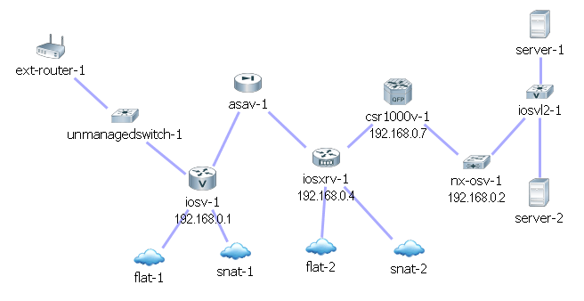
In order to cover all the subtypes and study their specific characteristics in the XML file, I created a network comprised of one of each subtype devices come with VIRL server installation. They include IOSv, IOSvL2, ASAv, CSR1000v, IOS XRv, NX-OSv and Linux servers.
Here is how the topology looks like:
Locating the topology file
In a standard installation, VM Maestro stores all the topology files at C:\Users\user-name\vmmaestro\workspace\My Topologies\.
The .virl file is written in clear text XML format. You can open it in any text editor such as Notepad. Extensible Markup Language (XML) is a markup language that defines a set of rules in hierachilcal fashion, for configuraitons in a format which is both human-readable and machine-readable. The design goals of XML emphasize simplicity, generality and usability across the Internet.
High level .virl file structure
topology
node 1
- extensions
   - entry1 node configuration
   - entry2 key type definitions
- interface 1
- interface 2
- interface 3
...
node 2
node 3
...
Connection 1
Connection 2
Connection 3
...
end of topology
Breaking down each session, it is not hard to understand meaning of each session by looking into the content. Node name, type and subtype are defined in the line below, as well as the router’s loopback IP and the coordinate on the canvas map.
<node name="iosv-1" type="SIMPLE" subtype="IOSv" location="265,225" ipv4="192.168.0.1">The next session is called “extensions”, where router’s configuration and some other attributes are stored. As you can see the configuration below was generated by AutoNetkit with a time stamp. If you choose to use your own configution, you can insert your own.
<extensions>
<entry key="config" type="string">! IOS Config generated on 2015-07-22 16:12
! by autonetkit_0.15.3
hostname iosv-1
boot-start-marker
boot-end-marker
!
no aaa new-model
!
ip cef
ipv6 unicast-routing
ipv6 cef
!
service timestamps debug datetime msec
service timestamps log datetime msec
no service password-encryption
no service config
enable password cisco
ip classless
ip subnet-zero
no ip domain lookup
line vty 0 4
transport input ssh telnet
exec-timeout 720 0
password cisco
login
line con 0
password cisco
!
no cdp run
!
interface Loopback0
description Loopback
ip address 192.168.0.1 255.255.255.255
!
interface GigabitEthernet0/0
description OOB Management
! Configured on launch
no ip address
duplex auto
speed auto
no shutdown
! omitted for brevity

</entry>
<entry key="AutoNetkit.mgmt_ip" type="string"></entry>
</extensions>
After the configuration is defined, VIRL needs to know how many interfaces the router has and what IP address you want to assign to each interface. You must start from Interfac ID 0 and increment sequentially. In this example, interface Gig0/1 has IP 10.0.0.2 with network prefix length of 16, which translates to subnet mask 255.255.0.0.
<interface id="0" name="GigabitEthernet0/1" ipv4="10.0.0.2" netPrefixLenV4="16"/>
<interface id="1" name="GigabitEthernet0/2" ipv4="10.1.0.1" netPrefixLenV4="30"/>
<interface id="2" name="GigabitEthernet0/3"/>
<interface id="3" name="GigabitEthernet0/4"/>
Then you define the next node and so on. At the end of the configuration, we need to let VIRL know how these nodes are inter-connected to each other. In a simulation, each node is assigned with a node ID, so does each interface. In the example below, “note [6]’s interface[1] connects to note[13]’s interface 1”. That’s it. VIRL doesn’t care if it was a FastEthernet or Gig Ethernet port. It only goes by interface IDs.
<connection dst="/virl:topology/virl:node[6]/virl:interface[1]" src="/virl:topology/virl:node[13]/virl:interface[1]"/>
<connection dst="/virl:topology/virl:node[6]/virl:interface[6]" src="/virl:topology/virl:node[1]/virl:interface[1]"/>
<connection dst="/virl:topology/virl:node[7]/virl:interface[1]" src="/virl:topology/virl:node[1]/virl:interface[2]"/>
<connection dst="/virl:topology/virl:node[2]/virl:interface[1]" src="/virl:topology/virl:node[7]/virl:interface[2]"/>
<connection dst="/virl:topology/virl:node[3]/virl:interface[1]" src="/virl:topology/virl:node[2]/virl:interface[2]"/>
<connection dst="/virl:topology/virl:node[4]/virl:interface[1]" src="/virl:topology/virl:node[3]/virl:interface[2]"/>
<connection dst="/virl:topology/virl:node[8]/virl:interface[1]" src="/virl:topology/virl:node[4]/virl:interface[2]"/>
<connection dst="/virl:topology/virl:node[5]/virl:interface[1]" src="/virl:topology/virl:node[8]/virl:interface[2]"/>
<connection dst="/virl:topology/virl:node[14]/virl:interface[1]" src="/virl:topology/virl:node[8]/virl:interface[3]"/>
<connection dst="/virl:topology/virl:node[1]/virl:interface[3]" src="/virl:topology/virl:node[9]/virl:interface[1]"/>
<connection dst="/virl:topology/virl:node[2]/virl:interface[4]" src="/virl:topology/virl:node[12]/virl:interface[1]"/>
<connection dst="/virl:topology/virl:node[1]/virl:interface[4]" src="/virl:topology/virl:node[11]/virl:interface[1]"/>
<connection dst="/virl:topology/virl:node[2]/virl:interface[3]" src="/virl:topology/virl:node[10]/virl:interface[1]"/>
That’s the overall structure of a .virl topology file. Before we move on, I’d like to show you the how those “special nodes” are defined in the .virl file.
A FLAT could is defined as ASSET and has a single interface called “link0” connected to a router. The SNAT cloud is configured the same way.
<node name="flat-1" type="ASSET" subtype="FLAT" location="206,317">
<interface id="0" name="link0"/>
</node>
<node name="flat-2" type="ASSET" subtype="FLAT" location="399,305">
<interface id="0" name="link0"/>
</node>
<node name="snat-1" type="ASSET" subtype="SNAT" location="300,310">
<interface id="0" name="link0"/>
</node>
<node name="snat-2" type="ASSET" subtype="SNAT" location="495,307">
<interface id="0" name="link0"/>
</node>
Similarly, an external router is defined as ASSET and it does not come with any configuration but its coordinates on the canvas and the interface ID.
<node name="ext-router-1" type="ASSET" subtype="EXT-ROUTER" location="74,76">
<interface id="0" name="link0"/>
</node>
Here comes to the fun part. A Linux server is confiugred using cloud-init techology. All the critical aspects of a server are specified in the configuration file.
<node name="server-2" type="SIMPLE" subtype="server" location="635,238" vmFlavor="m1.small [2]">
<extensions>
<entry key="config" type="string">#cloud-config
bootcmd:
- ln -s -t /etc/rc.d /etc/rc.local
hostname: server-2
manage_etc_hosts: true
runcmd:
- start ttyS0
- systemctl start [email protected]
- systemctl start rc-local
- sed -i '/^\s*PasswordAuthentication\s\+no/d' /etc/ssh/sshd_config
- echo "UseDNS no" >> /etc/ssh/sshd_config
- service ssh restart
- service sshd restart
users:
- default
- gecos: User configured by VIRL Configuration Engine 0.15.8
lock-passwd: false
name: cisco
plain-text-passwd: cisco
shell: /bin/bash
ssh-authorized-keys:
- VIRL-USER-SSH-PUBLIC-KEY
sudo: ALL=(ALL) ALL
write_files:
- path: /etc/init/ttyS0.conf
owner: root:root
content: |
# ttyS0 - getty
# This service maintains a getty on ttyS0 from the point the system is
# started until it is shut down again.
start on stopped rc or RUNLEVEL=[12345]
stop on runlevel [!12345]
respawn
exec /sbin/getty -L 115200 ttyS0 vt102
permissions: '0644'
- path: /etc/systemd/system/[email protected]
content: |
[Unit]
Description=Run dhclient on %i interface
After=network.target
[Service]
Type=oneshot
ExecStart=/sbin/dhclient %i -pf /var/run/dhclient.%i.pid -lf /var/lib/dhclient/dhclient.%i.lease
RemainAfterExit=yes
owner: root:root
permissions: '0644'
- path: /etc/rc.local
owner: root:root
permissions: '0755'
content: |-
#!/bin/sh -e
ifconfig eth1 up 10.1.128.3 netmask 255.255.255.248
route add -net 10.1.0.0/16 gw 10.1.128.1 dev eth1
route add -net 192.168.0.0/28 gw 10.1.128.1 dev eth1
exit 0As you saw you can specify the server size, file system permissions, user accounts, interface IP addresses, routing table and etc. For the most part, we only care about the interface IPs and routing table. That’s all we essentially needed for the servers to function as a user workstation or a utility server to test the network connectivity.
Import and export network topology files
As mentioned in the beginning of the session, VIRL’s topology file contains all the information to launch a simulation. That has made the simulation highly portable, meaning that you can copy the .virl from one environment to another, import the .virl file and you are good to go.
Let’s start with exporting a topology file from VM Maestro. There are two ways to do it. The easiest and most straightforward way is just go to the topology folder and copy the .virl file. The topology folder is typically located at C:\Users\user-name\vmmaestro\workspace\My Topologies\.
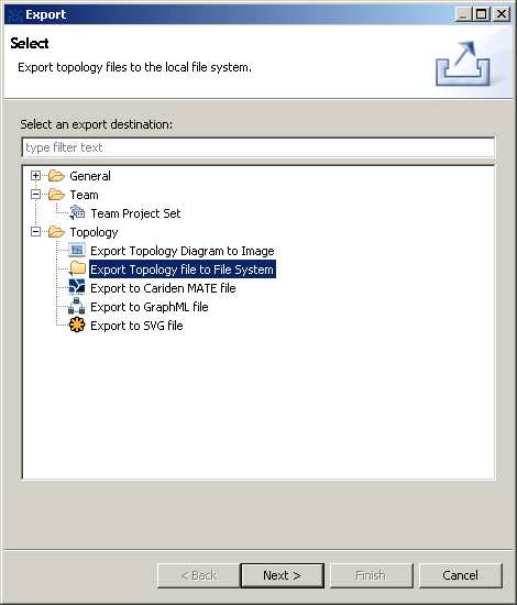
You can also go to Maestro’s menu, File – Export. And select “Export Topology file to File System”. And go through the wizard.
Importing a .virl file works in the same fashion. You can either copy over the .virl file or go through the import wizard on Maestro menu, File – Import.
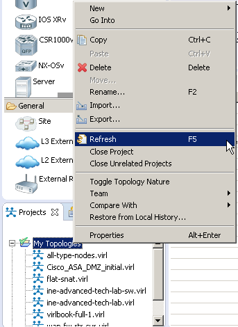
After the new .virl topology files are imported, it is important to note that you need to refresh “My Topologies” folder in Projects panel to see the imported file. VM Maestro does not refresh the files automatically.
I’d love to hear from you!
If you have any questions regarding the content, feedback or suggestions for future topics, please leave a comment below.
Excellent doc thanks